Decomposing a DeviceN colorant list
This page applies to Harlequin v13.1r0 and later; both Harlequin Core and Harlequin MultiRIP.
The [RB3] and [PDF1.6] specifications say that /DeviceN color spaces must use the tint transform to convert colors to the alternate space when at least one of the components is not renderable on the output device. The RIP’s handling of /DeviceN color spaces differs significantly from this.
The primary aim of /DeviceN color management in the RIP is to make objects painted in a /DeviceN color space appear the same as a /Separation, /DeviceCMYK, or /DeviceGray color space where appropriate. In particular, if a /DeviceN color space contains a mixture of CMYK and spots:
- if the only non-zero value is for a spot, the output should match the color managed spot from named color management, if used, see Named color management.
- if the only non-zero values are for CMYK, the output should match the color managed CMYK. If the
/DeviceNcomponents contain a subset of CMYK, these are converted to CMYK and then color managed. - if overprint is on in the gstate, the missing CMYK components are handled the same as CMYK non-zero overprints; the overprints are simulated or converted colorimetrically depending on the current
OveprintPreviewmode and the current transparency group. This is explained in Understanding OverprintPreview. - there should be no artifacts in blends painted in a color managed
/DeviceNcolor space.
In brief, the RIP decomposes the /DeviceN components and creates potentially multiple color pipelines, each of which convert color to the output space. The final color results from blending of colors from the multiple pipelines. More detail follows.
The /DeviceN components are broken down into these classes, some of which may result in multiple color pipelines. The classes are processed in order:
Process colorants
If a subset of CMYK is present, it will be color managed as CMYK with missing components using zero color values. Otherwise, if Gray is present, it is color managed as Gray if CMYK or Gray has an intercept profile set. Red, Green, and Blue components are always treated as spot colorants by this part of the process. The color management of CMYK and Gray can be partially controlled using the AdobeProcessSeparations user param, as described in Process separations.
NextDevice colorants
Colorants that may be used as the input to any /NextDevice (see NextDevice named colorants). Such colorants are passed directly to the /NextDevice, bypassing the earlier parts of the color pipeline. They are color managed individually as Separation color spaces.
There can be any number of /NextDevice colorants.
Renderable colorants
Colorants that are renderable on the output device are treated as Separation spaces, that is, their color values are passed through unaltered. Colorants that are both /NextDevice colorants and present on the output device are treated as /NextDevice colorants for this purpose.
Intercepted colorants
These colorants are color managed individually as Separation color spaces. They are either:
- found in one of the NCD resources (see Named color management).
- found in a SpectralData PDF object which, if present, contains one or more CxF/X-4 files embedded within the PDF file.
There can be any number of intercepted colorants.
None colorants
These are discarded for the purpose of this component breakdown.
Other colorants
This contains the subset of the original list that is not handled by one of the above. They will be converted to the output space as a group using the original alternate space and tint transform, but with the color values of the handled colorants replaced with zero.
A set of color pipelines are available. The RIP takes one of these actions with them:
- If the
/DeviceNspace is being painted into the virtual device withOverprintPreviewin Inactive mode AND there are one or more Other colorants; the RIP ignores the component breakdown and revert to the using original alternate space and tint transform from the/DeviceNspace in the job. This is done because some jobs use None colorants as placeholders that actually contain color values for the alternate space, and this practice makes it impossible to separate the components. (IfOverprintPreviewis active and/or the/DeviceNis painted into an explicit transparency group, the original tint transform is not used.) - Otherwise, the colors produced by these pipelines are merged. They are usually merged as early as possible in the color pipeline.
Merging component color pipelines
Depending on the color configuration, the set of color pipelines for the /DeviceN components possibly has some pipeline elements in common. In particular, if the configuration contains a /NextDevice entry in setreproduction, two or more of the pipelines are likely to share the same /NextDevice entry. When this happens, the colors are merged early, before passing them to the shared /NextDevice entry. If possible, all of the color pipelines are merged early before the same /NextDevice entry.
If early merging is not possible, colors are merged late at the end of the pipeline. No matter whether the merging was early or late, the result is a single-color value for the original /DeviceN space.
The biggest advantage in early merging is that the colors resulting from early merging are often superior, and can be very different from those resulting from late merging. For example, if a /NextDevice entry contained an ink limiting module, the ink limiting would be most useful if it acted on a single color for the whole /DeviceN space. If the merging were done late, the ink limiting would only act on individual pipelines, and the late merged colors could easily exceed the ink limits of the device.
Use the ID and AllowColorManagement keys to control the merging of colors from the NCDs, see Named color database resources.
- For an NCD with a device space ColorSpace entry that also has an ID key, its colors are merged with the matching
NextDevicetransform, bypassing any preceding transforms. This allows NCDs to be merged with the most appropriate printing condition in the case of color pipelines with severalNextDevicetransforms, each with different printing conditions. - Otherwise, for an NCD with a
/DeviceNor/SeparationColorSpace entry that also has theirAllowColorManagemententry set tofalse, its colors are merged late at the end of the pipeline. NCDs with these settings should convert to colors in the output device space.
After taking account of the white point, colors are merged using a multiply blend between values of each component.
Illustrations of normal pipeline merging
The actual merging of component color pipelines for any given /DeviceN color space has many variables, but the principal features are illustrated in Figure: Single Transform DeviceN Decomposition to CMYK Device, Figure: Two Transform DeviceN Decomposition to N-Color Device, and Figure: DeviceN Decomposition to N-Color Device with NextDevice Spots (all appear below).
In these figures, each component pipeline contains up to three color transforms, labeled as Process Colorant Transform, NextDevice Transform, and NextDevice Spots Transform. To simplify the figures, only the transforms are shown. The profiles used within each of these transforms are not important to the merging process, except that pipelines can only be merged if they use the same profiles.
Figure: Process Colorant Transform (below) shows a generic expansion of the Process Colorant Transform.
The NextDevice Transform could be one of the examples used elsewhere in this section. The NextDevice Spots Transform could be the example from Figure: NextDevice Spots (below).
The following figures illustrate the component color pipelines before merging in the top part, with the pipeline after merging shown in the bottom part.
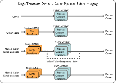
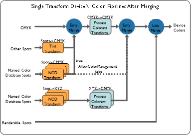
Figure: Single Transform DeviceN Decomposition to CMYK Device
Figure: Single Transform DeviceN Decomposition to CMYK Device shows the pipelines for a /DeviceN color space in a configuration without a /NextDevice transform.
Most of the component pipelines contain a single-color transform. The exception is for CMYK NCDs with AllowColorManagement false, which provides colors in device space. The merged pipeline shows that most of the component pipelines are merged as early as possible, while renderable spots are merged late, at the end of the pipeline.
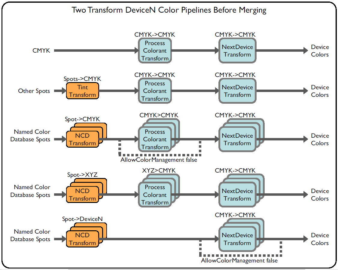
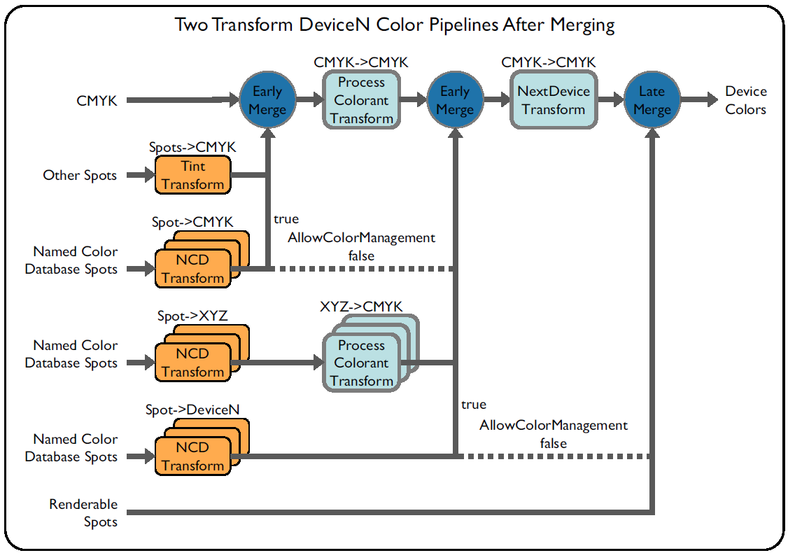
Figure: Two Transform DeviceN Decomposition to N-Color Device
Figure: Two Transform DeviceN Decomposition to N-Color Device shows the pipelines for a /DeviceN color space in a configuration with a /NextDevice. Most of the component color pipelines contain two color transforms.
The exceptions are for:
- CMYK NCDs with
AllowColorManagementfalse, which bypass the process colorant transform, /DeviceNNCDs that always bypass the process colorant transform. In the figure, theDeviceNNCD isDeviceNwith CMYK colorants, which is early merged with the first NextDevice transform that accepts CMYK.- For
/DeviceNNCDs whenAllowColorManagementtrue, the CMYK component is subject to the CMYK intercept profile. /DeviceNNCDs withAllowColorManagementfalse, which provide colors in device space. The merged pipeline shows that most of the component pipelines are merged as early as possible, while renderable spots and/DeviceNNCDs are merged late, at the end of the pipeline.
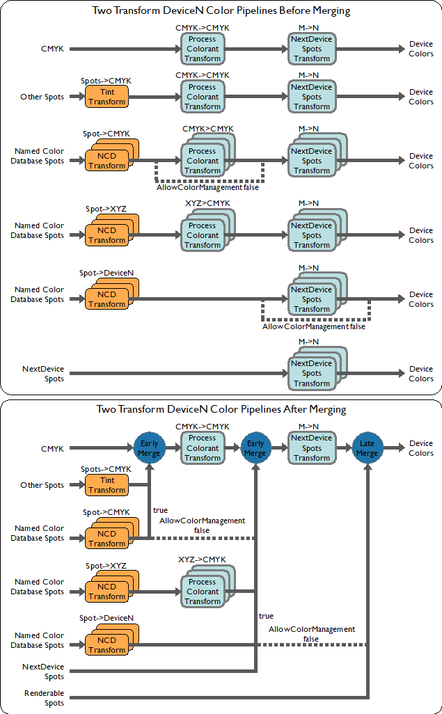
Figure: DeviceN Decomposition to N-Color Device with NextDevice Spots
Figure 17.15 shows the pipelines for a /DeviceN color space in a configuration with two /NextDevice transforms that accept NextDevice spots. In this configuration, the first NextDevice transform accepts the spots S1 and S2, which are treated as NextDevice spots. The same transform converts CMYK+S1+S2 to CMYKOG.
Most of the component color pipelines contain three color transforms. The exceptions are the same as Figure: Two Transform DeviceN Decomposition to N-Color Device, NextDevice spots, with the addition of NextDevice spots, which are sent to the first NextDevice transform that accepts them, bypassing earlier transforms in the pipeline.
The merged pipeline shows that most of the component pipelines are merged as early as possible, while renderable spots and /DeviceN NCDs are merged late, at the end of the pipeline.
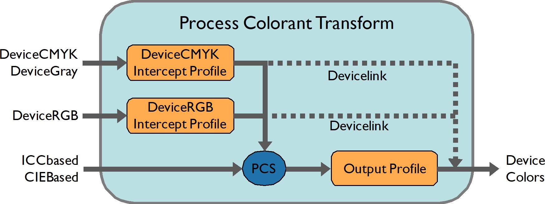
Figure: Process Colorant Transform
Illustrations of controlled merging of spots with color pipelines
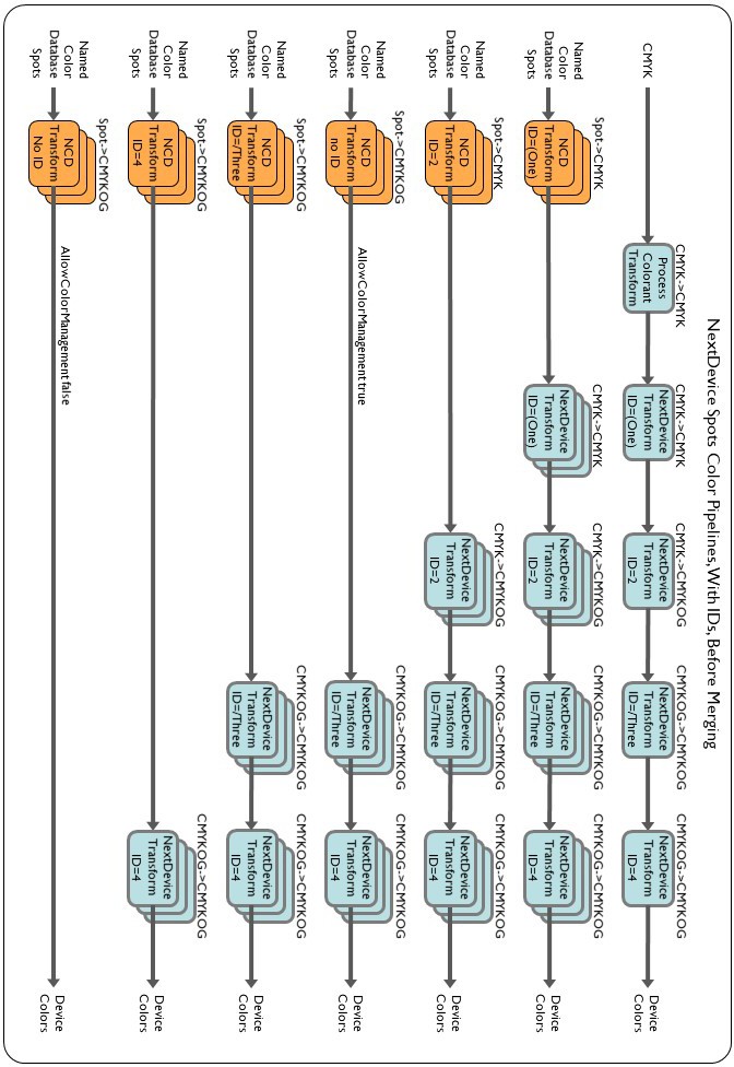
Figure: Color pipelines before merging
Figure 17.17 shows the pipelines for various NCDs in a contrived color configuration containing four /NextDevice transforms and several NCDs with different color spaces and ID keys, purely to illustrate how NCD ID matching works. Each /NextDevice transform has an ID key, which matches one of the NCDs in this configuration. There are also two NCDs without an ID key to illustrate early merging and require NCD colorants to match the /NextDevice transform.
For all the NCDs with ID keys, colors are sent directly to the matching /NextDevice and bypass some transforms in the pipeline.
For the NCD with no ID and AllowColorManagement=true, the CMYKOG colors are sent directly to the first /NextDevice that accepts CMYKOG.
For the NCD with no ID and AllowColorManagement=false, the CMYKOG colors are merged late at the end of the pipeline.
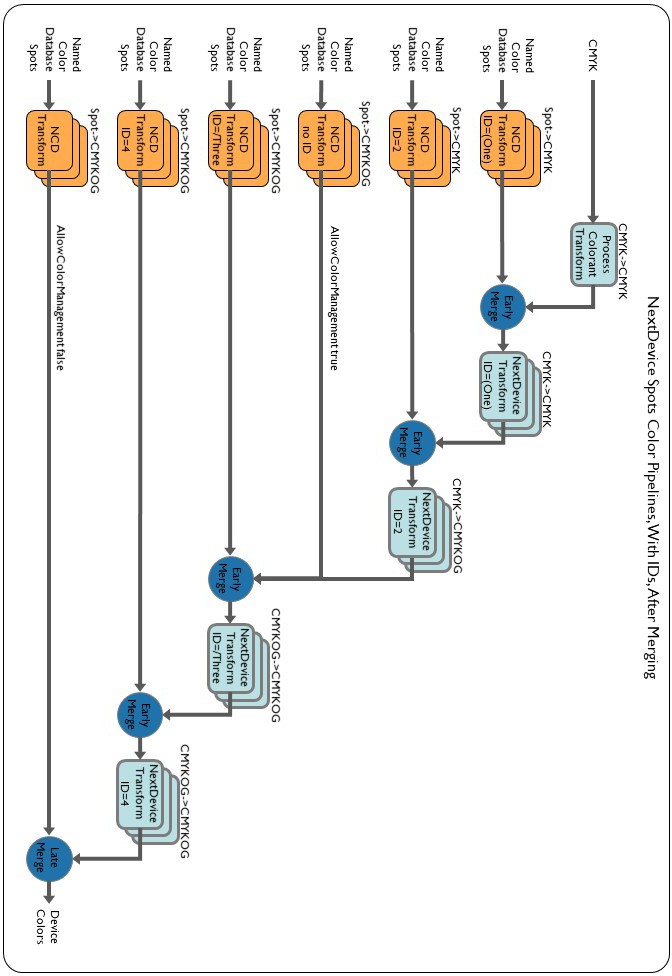
Figure: Color pipelines after merging
Assuming that the color pipelines in are merged together in the same DeviceN color space, shows the result of the merging.
