Hqn094 - Mixing multi-bit screens
Introduction
The Harlequin RIP supports halftoning on output devices with multiple droplet sizes or exposure levels by producing 2-bit or 4-bit deep output rasters. Each device pixel holds an output value from 1 to 3 or 15 representing the droplet size or the exposure level, or 0 for white.
Note: From v11.0r5 the "MLS-Mix" license feature is required to use Type 1009 half-tones.
The PostScript Language specification (PostScript Language Reference Manual—Section 7.4.5) describes a simplistic generalization of 1-bit screens to multi-bit output. The PDF specification (PDF ISO 32000-1 standard—Section 10.6.4) has the same description. It takes all 4 or 16 representable output values, and uses the usual 1-bit algorithm to determine whether to use the next lower or next higher output value. This has the effect of repeating the progression of screen patterns 3 or 15 times across the entire tint range. Shown below is a sample of this with a very coarse screen:

Example 1.a
This is not very useful on practical devices. From v11, the Harlequin RIP has new controls to influence how output pixel values are employed, including:
- using a subset of the output pixel values available at the given bit depth;
- limiting the maximum amount of an output value that the RIP employs;
- overlapping the introduction of a darker output value with the end of the preceding lighter output value;
- use a different screen for each output value.
This is achieved using the type 1009 halftone. Note that the Harlequin RIP uses an extension to the PostScript language halftone dictionaries; see the Extensions manual for more information. The Harlequin RIP also has an earlier, less sophisticated feature for specifying an entire multi-bit screen as an extended threshold array. For more information see Technical Note Hqn061—"Using Threshold Screens".
Mix with type 1009
A type 1009 halftone dictionary contains, as the value of the /Mix key, an array of dictionaries, where each entry in the array influences how and when the RIP will employ one specific output pixel value out of all the available non-zero values. Typically, all entries use the same underlying screen, to effect a slight modification of the default behaviour described in the standard, but this also allows mixing entirely different screens.
In a 2-bpp output raster, every pixel can take on one of three possible nonzero values: 3, 2 and 1 (from darkest to lightest). So, in its simplest form, a /Mix for 2-bpp output will be a three-element array, specifying the same screen in each, and describing the use of the output pixel values (in order from darkest to lightest).
For example:
<< /HalftoneType 1009 % mix
   /HalftoneName (homogeneous)
   /Mix
   [ << /HalftoneType 1
        /SpotFunction /Euclidean
        /Frequency 80 /Angle 45
        /Level 3        % Output pixel value 3 (darkest)
        /TransitionFunction
            << /FunctionType 2
               /Domain [0.0 0.32] /Range [0.0 1.0]
               % /N 1 specifies a linear interpolation.
               % These /C0 & /C1 values give function values of
               % 1.0 at tint 0.0 and 0.0 at tint 0.32.
               /N 1 /C0 [1.0] /C1 [-2.125] >> >>
     << /HalftoneType 1
        /SpotFunction /Euclidean
        /Frequency 80 /Angle 45
        /Level 2        % Output pixel value 2
        /TransitionFunction
            << /FunctionType 2
               /Domain [0.30 0.57] /Range [0.0 1.0]
               % These /C0 & /C1 values give function values of
               % 1.0 at tint 0.30 and 0.0 at tint 0.57.
               /N 1 /C0 [2.111] /C1 [-1.593] >> >>
     << /HalftoneType 1
        /SpotFunction /Euclidean
        /Frequency 80 /Angle 45
        /Level 1        % Output pixel value 1 (lightest)
        /TransitionFunction
            << /FunctionType 2
               /Domain [0.54 1.0] /Range [0.0 1.0]
               % These /C0 & /C1 values give function values of
               % 1.0 at tint 0.54 and 0.0 at tint 1.0.
               /N 1 /C0 [2.174] /C1 [0.0] >> >>
   ]
>>
Where the /TransitionFunction keys supply the functions that describe how the coverage of that output pixel value changes depending on the tint being painted. The /Domain key gives the tint range over which the coverage changes; outside that, it remains at the value at the edge of the /Domain. In the above example, the lightest screen increases from 0% coverage at white to 100% coverage at tint 0.54 or 46% grey (and onwards, though gradually replaced by darker values).
Type 2 functions are used to describe linear increases across the entire range. A practical screen would typically need more complicated functions, at least consisting of multiple linear pieces with different gradients. This can be done by a combination of type 3 and type 2 functions. To facilitate this, a procset called HqnHalftoneUtilities is provided containing a procedure for building such piecewise linear functions.
piecewiselineargen takes a description of a continuous, piecewise linear function and returns a function dictionary that computes that function. The description is an array [ X0 Y0 X1 Y1 ... ], listing the corner points. Now, the same screen using piecewiselineargen:
<< /HalftoneType 1009 % mix
   /HalftoneName (homogeneous-pwl)
   /Mix
   [ << /HalftoneType 1
        /SpotFunction /Euclidean
        /Frequency 80 /Angle 45
        /Level 3        % Output pixel value 3 (darkest)
        /TransitionFunction
          [0.0 1.0  0.32 0.0]
          /HqnHalftoneUtilities /ProcSet findresource
             /piecewiselineargen get exec
     >>
     << /HalftoneType 1
        /SpotFunction /Euclidean
        /Frequency 80 /Angle 45
        /Level 2        % Output pixel value 2
        /TransitionFunction
          [0.30 1.0  0.57 0.0]
          /HqnHalftoneUtilities /ProcSet findresource
             /piecewiselineargen get exec

     >>
     << /HalftoneType 1
        /SpotFunction /Euclidean
        /Frequency 80 /Angle 45
        /Level 1        % Output pixel value 1 (lightest)
        /TransitionFunction
          [0.54 1.0  1.0 0.0]
		 /HqnHalftoneUtilities /ProcSet findresource
             /piecewiselineargen get exec
     >>
   ]
>>
Non-linear functions can be built using type 4 functions, which allow the function to be described using a PostScript language expression. Type 4 functions are only specified for PDF, but the Harlequin RIP also supports them in the PostScript language. Also, since the RIP contains a full PostScript language interpreter, it lifts the PDF restriction to a set of allowed operators and allows any PostScript language code, provided it behaves as a pure mathematical function, that is, its results depend only on the arguments, with no side effects. Such a function might look like this:
<< /FunctionType 4
   /Domain [0.0 0.32] /Range [0.0 1.0]
   /DataSource
   ({ 0.32 exch sub 0.32 div 1.07 exp }) cvx
>>
Not using every possible output value
Some devices don't really employ all the possible output pixel values, so you can use fewer dictionaries in the type 1009 halftone dictionary (with an appropriate /Level key in each) to make the RIP produce just a subset of the values.
For example, you could use something like the following for a 2-bpp device that only actually uses pixel values 1 and 3:
<< /HalftoneType 1009 % mix
   /HalftoneName (homogeneous_1_3)
   /Mix
   [ << /HalftoneType 1
        /SpotFunction /Euclidean
        /Frequency 80 /Angle 45
        /Level 3        % Output pixel value 3 (darkest)
        /TransitionFunction
          [0.0 1.0  0.42 0.0]
          /HqnHalftoneUtilities /ProcSet findresource
             /piecewiselineargen get exec
     >>
     << /HalftoneType 1
        /SpotFunction /Euclidean
        /Frequency 80 /Angle 45
        /Level 1        % Output pixel value 1 (lightest)
        /TransitionFunction
          [0.40 1.0  1.0 0.0]
          /HqnHalftoneUtilities /ProcSet findresource
             /piecewiselineargen get exec
     >>
   ]
>>
The dictionaries in the array must still be in descending order of /Level.
Not using the darkest part of an output value
You can specify a function whose values stop short of 1.0 to limit the screen to less than 100% of the given output value. That is, prevent it from setting every pixel in the output to the same value, so that each level never achieves a complete solid fill. For example (like homogeneous-pwl above, but with limits):
<< /HalftoneType 1009 % mix
   /HalftoneName (homogeneous_limit)
   /Mix
   [ << /HalftoneType 1
        /SpotFunction /Euclidean
        /Frequency 80 /Angle 45
        /Level 3        % Output pixel value 3 (darkest)
        /TransitionFunction
          % limiting this level to 65%
          [0.0 0.65  0.32 0.0]
          /HqnHalftoneUtilities /ProcSet findresource
             /piecewiselineargen get exec
     >>
     << /HalftoneType 1
        /SpotFunction /Euclidean
        /Frequency 80 /Angle 45
        /Level 2        % Output pixel value 2
        /TransitionFunction
          % limiting this level to 80%
          [0.30 0.80  0.57 0.0]
          /HqnHalftoneUtilities /ProcSet findresource
             /piecewiselineargen get exec
     >>
     << /HalftoneType 1
        /SpotFunction /Euclidean
        /Frequency 80 /Angle 45
        /Level 1        % Output pixel value 1 (lightest)
        /TransitionFunction
          % limiting this level to 90%
          [0.54 0.90  1.0 0.0]
          /HqnHalftoneUtilities /ProcSet findresource
             /piecewiselineargen get exec
     >>
   ]
>>
Example 1.b
Not using the lightest part of an output value
You can specify a function whose values start above 0.0 to avoid using the lightest part of the screen for this output value. You can modify the second value in the array passed to piecewiselineargen to specify the base value for the output value. The use of this output value will start directly from the specified coverage, instead of building up from 0%. This is can be useful at the lightest level, where a few sparse faint dots may just give the effect of "scum" on the page, rather than a light tint.
Adding overlap between output values
Usually you would want the pixels of a darker output value to start to appear before the pixels of the lighter output value have reached their specified limit. This can avoid the appearance of bands across shaded fills where one output value reaches 100% coverage.
This is achieved by overlapping the /Domains. The above examples do that, but in a simplistic way that produces a jagged density curve. You will want to adjust the functions to increase slower in the overlap, because the effective gradient (of both levels taken together) is larger. This is where defining them piecewise is useful.
Note how adjacent functions both define a separate piece for their overlap.
For example:
<< /HalftoneType 1009 % mix
   /HalftoneName (overlapped)
   /Mix
   [ << /HalftoneType 1
        /SpotFunction /Euclidean
        /Frequency 80 /Angle 45
        /Level 3        % Output pixel value 3 (darkest)
        /TransitionFunction
          [0.0 1.0  0.38 0.04  0.42 0.0]
          /HqnHalftoneUtilities /ProcSet findresource
             /piecewiselineargen get exec
     >>
     << /HalftoneType 1
        /SpotFunction /Euclidean
        /Frequency 80 /Angle 45
        /Level 1        % Output pixel value 1 (lightest)
        /TransitionFunction
          [0.38 1.0  0.42 0.973  1.0 0.0]
          /HqnHalftoneUtilities /ProcSet findresource
             /piecewiselineargen get exec
     >>
   ]
>>
So in the example above, pixel value 1 reaches 97.3% coverage at tint 0.42 and 100% at 0.38 (though some pixels have been replaced by value 3 by that point). Pixel value 3 starts from 0% at tint 0.42 and reaches 4% coverage at tint 0.38.
Note that while calibration can stretch and compress the color ranges to compensate for slight variations in the density gradient of the mixed screen, it cannot change the proportions of the two screens in an overlap. Therefore, choosing the rates of the two functions in the overlap is critical to achieving a smooth mix.
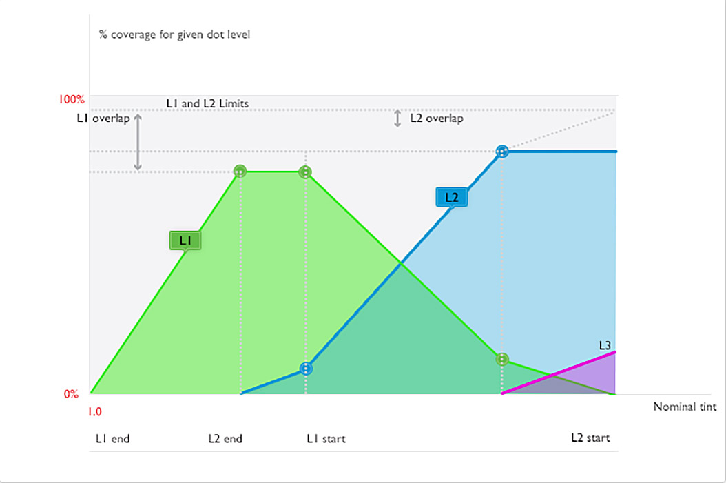
Example 1.c
This graphic demonstrates the effect of overlaps (in a general way, not trying to illustrate any of the examples). It shows (a part of) three levels interacting and modifying each other's effective coverage.
The darker levels are gradually covering up the lighter ones. So, even though level 1's coverage is nominally increasing all the way to L1 start, the effective coverage is almost constant in the overlap with level 2, where both levels are adding pixels. Above L1 start, its effective coverage declines as there are no new L1 pixels.
Even though the overlaps are small, adjacent levels are present over a large tint range, and it is not unusual to have three levels present at the same tint (as between L3 end and L2 start here).
Note how the linear pieces of the different levels are chosen to align to each other, so that the total density can be made to increase smoothly.
Mixing different screens
In addition to mixing copies of the same screen, you can use a different screen for each output pixel value. However, for the RIP to be able to automatically construct a mixed screen, the component screens must have the same cell dimensions.
For threshold screens, this means the size parameters (/Width, /Height, /Xsquare etc.) must be the same. The cell sizes of spot functions depend on the frequency and the angle only, so those must match (which is what you'd want anyway). It is technically possible to mix threshold and spot functions in the same mix, but this requires knowledge of the implementation details and a certain amount of modification of the screens themselves.
Please contact Global Graphics if you need advice on designing sophisticated screens.
Example 1
This example is for a 4-bit output raster (/ValuesPerComponent 16), but uses just 5 of the possible 15 non-zero output pixel values available with 4 bpp. The screen is based on one of the RIP's HDS (dispersed) screens. It is assumed that the droplet sizes suggests cross- over points at 40%, 72%, 80% and 88%, and makes them smooth by overlapping the levels. This would be expressed as:
<< /HalftoneType 1009 % mix
   /HalftoneName /Example1Overlaps
   /Mix
   [ << /HalftoneType 199 /Halftone /Hds-d-gen /HalftoneColor /D
        /Level 14
        /TransitionFunction
          [0.0 1.0  0.100 0.138  0.132 0.0]
          /HqnHalftoneUtilities /ProcSet findresource
             /piecewiselineargen get exec
     >>
     % about 24%/28% overlap between these levels
     << /HalftoneType 199 /Halftone /Hds-d-gen /HalftoneColor /D
        /Level 12
        /TransitionFunction
          [0.100 1.0  0.132 0.813  0.187 0.170  0.216 0.0]
          /HqnHalftoneUtilities /ProcSet findresource
             /piecewiselineargen get exec
     >>
     % about 25%/28% overlap between these levels
     << /HalftoneType 199 /Halftone /Hds-d-gen /HalftoneColor /D
        /Level 9
        /TransitionFunction
          [0.187 1.0  0.216 0.820  0.274 0.099  0.290 0.0]
          /HqnHalftoneUtilities /ProcSet findresource
             /piecewiselineargen get exec
 	 >>
     % about 16%/5% overlap between these levels
     << /HalftoneType 199 /Halftone /Hds-d-gen /HalftoneColor /D
        /Level 6
        /TransitionFunction
          [0.274 1.0  0.290 0.975  0.580 0.063  0.620 0.0]
          /HqnHalftoneUtilities /ProcSet findresource
             /piecewiselineargen get exec
     >>
     % about 12%/10% overlap between these levels

     << /HalftoneType 199 /Halftone /Hds-d-gen /HalftoneColor /D
        /Level 3
        /TransitionFunction
          [0.580 1.0  0.620 0.950  1.0 0.0]
          /HqnHalftoneUtilities /ProcSet findresource
             /piecewiselineargen get exec
     >>
  ]
>>
Example 1.d
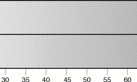
Example 1.d shows the first crossover point—in the upper part can be seen the result without the overlaps; a distinct band can be seen wherein all the pixels are the same value. By contrast, the lower part shows the much smoother looking transition when overlap is added. 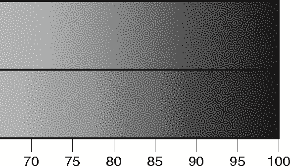
Example 1.e
Example 1.e shows the remaining crossover points—again, the three noticeable bands in the upper part are far less obvious in the lower part because overlaps are used.
This simple example uses a single halftone dictionary, as you would for monochrome output. For a multiple colorants, you would use a type 1009 dictionary as each subordinate dictionary of a /HalftoneType 5 halftone.
/HalftoneName is not mandatory, but it does appear in the screening messages in the RIP monitor as "Dot shape", which can be useful. For example:
Dot shape: 'Example1Overlaps'  Component: Gray
Levels:  [14] 100.00 - 86.80  [12] 90.00 - 78.40  [9] 81.30 - 71.00  [6]
 72.60 - 38.00  [3] 42.00 -  0.00
Tones used: 1024/1024
Colorants: 'Gray'
Example 2
Example 2 shows the use of /Halftone 1009 on a normal spot-function AM screen.
/Example2_SF { dup mul exch dup mul 0.5 mul add 1 exch sub } bind def
<< /HalftoneType 1009 % mix
   /HalftoneName /Example2
   /Mix   [ << /HalftoneType 1
        /SpotFunction /Example2_SF load
        /Frequency 12 /Angle 75
        /Level 3
        /TransitionFunction
          [0.0 1.0  0.360 0.151  0.488 0.0]
          /HqnHalftoneUtilities /ProcSet findresource
             /piecewiselineargen get exec
     >>
     << /HalftoneType 1
        /SpotFunction /Example2_SF load
        /Frequency 12 /Angle 75
        /Level 2
        /TransitionFunction
          [0.360 1.0  0.488 0.800  0.698 0.142  0.789 0.0]
          /HqnHalftoneUtilities /ProcSet findresource
             /piecewiselineargen get exec
     >>
     << /HalftoneType 1
        /SpotFunction /Example2_SF load
        /Frequency 12 /Angle 75
        /Level 1
        /TransitionFunction
          [0.698 1.0  0.789 0.537  1.0 0.0]
          /HqnHalftoneUtilities /ProcSet findresource
             /piecewiselineargen get exec
     >>
   ]
>>
sethalftone
Note: The frequency value is very low for illustration purposes.
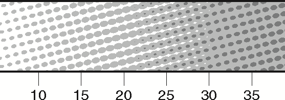
Example 2.a shows the first cross-over point, and again illustrates how the use of overlap means the darker output value starts to appear as a darkening of the center of the spot whilst the spots themselves still look like ellipses (albeit with one edge touching).
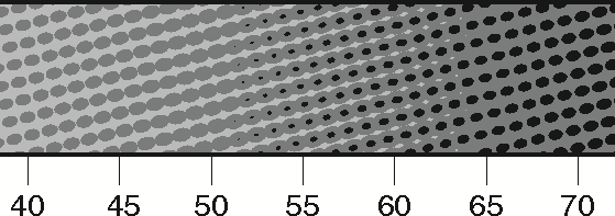
Example 2.b
Example 2.b shows the second cross-over point, and together these illustrations show how the screen retains its normal spot-shape feel over the whole range.
Example 2 assumes 2-bit output raster (/ValuesPerComponent 4).
Definitions of keys
Mix
(array, mandatory) Used in a type 1009 halftone dictionary, an array of halftone dictionaries, in descending order of (non- zero) output pixel value, each dictionary describing the screen for that output pixel value and containing /Level and /TransitionFunction keys describing how to mix that with the other levels.
Additional keys for subscreens of a type 1009
Level
(integer, optional) The output pixel value this parameter dictionary applies to.
Range: 1 to 3 for 2-bpp output raster; 1 to 15 for 4-bpp output raster.
Default: One less than the /Level for the previous item of the /Mix array. That is, one less than the next "darker" output pixel value.
Errors (other than typecheck)
The following will cause a rangecheck error:
-
/Levelout of the range set by the bit depth of the output device. - If the values of
/Leveldo not decrease in value.
TransitionFunction
(dictionary, mandatory) A function that describes how the coverage of this output pixel value changes depending on the tint being painted. (For details of functions, see PostScript Language Reference Manual—Section 3.10 and PDF ISO 32000-1 standard—Section 7.10.) The tint input is the standard PS/PDF tint from 0.0=black to 1.0=white. The coverage output goes from 0.0=0%=white to 1.0=100%=black.
The function must be monotonically decreasing, as the RIP only supports monotonic screens.
Therefore, the /Domain of the function gives the tint range over which the coverage changes; outside that, it remains at the value it has at the edge of the /Domain (as per the specification). You might set the /Range to declare the coverage values the function is producing, but you wouldn't usually use it to clip the output values, because that produces a kink in the density gradient of the mix.
Errors (other than typecheck)
The following will cause a rangecheck error:
- The function is not a 1-input, 1-output function.
- The code in a type 4 function does not consume a single argument and return a single value.
- The domain is not a sub-range of
[0.0 1.0]. - The range is not a sub-range of
[0.0 1.0].
The following will cause a VMerror:
- Running out of memory to cache function values.
The following will cause a configurationerror:
- Defining a screen with no overlaps at all.
