The Apex renderer allows spot colors to be merged with a rendered result (process colors) as a post-process. This allows for overprint simulation of spot components.
In Mako 8.0, the CRenderSpec::mergeSpotColors property is set with a list of spot colors to be merged
In Mako 8.1, this becomes a post-process that is added to CRenderSpec::postProcesses and specified by an IPostProcessSpec::CSpotMergePostProcessSpec that lists the spot colors to be merged
In both cases, the list is supplied as an IDOMColorSpaceDeviceN::CColorantInfoVect.
Custom spot merging - CustomSpotMergeProcessSpec
With custom spot merging, you as a developer have complete control over how spot colors are merged. For example, you could upload look-up tables as textures (data structures that a shader can refer to) then manipulate the color at the pixel level in what ever way you choose, merging the result with the underlying pixel. All on the GPU, and therefore very fast.
The code example ApexCustomSpotMergeExample demonstrates this capability.
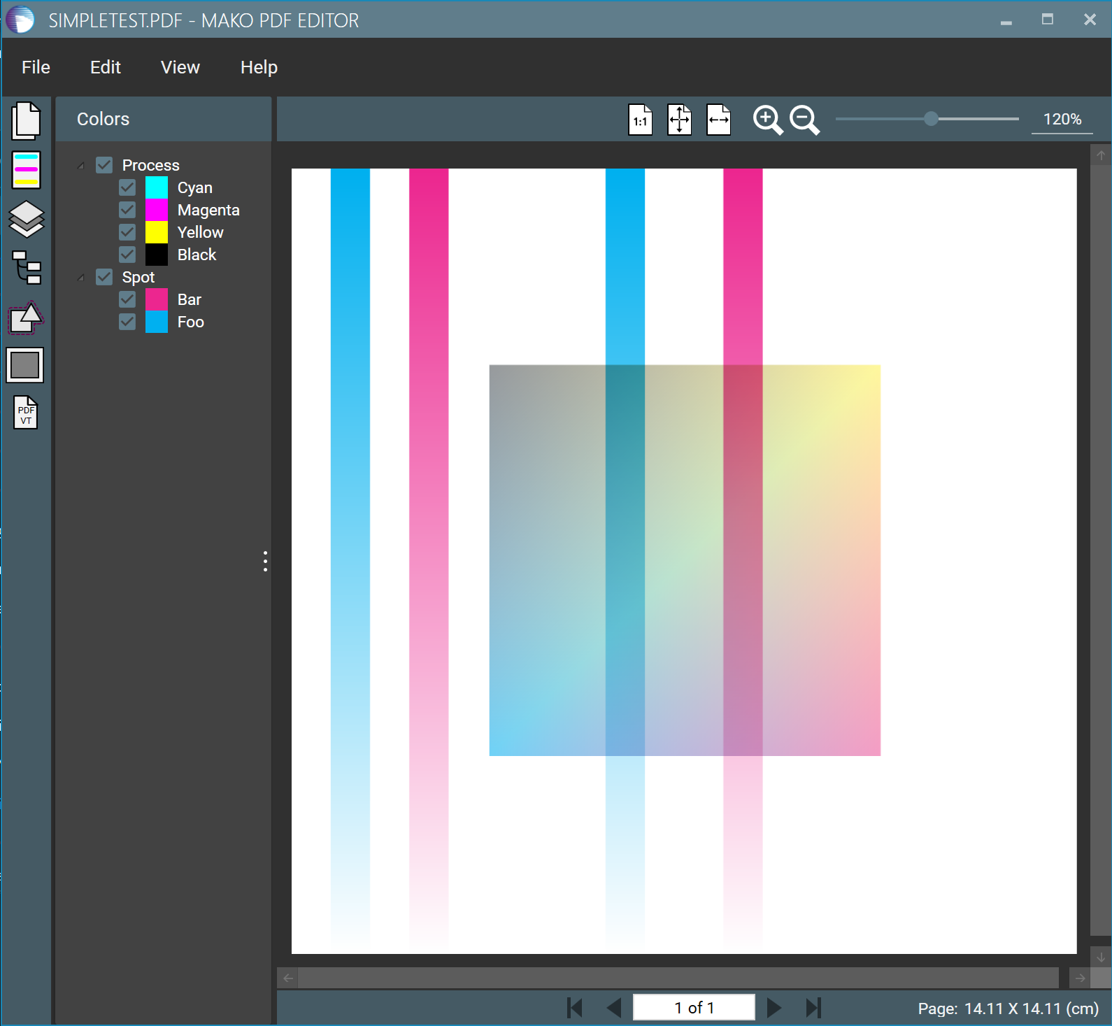
On the left is the original PDF, with two spot colors. Rendered normally (also with Apex), the two spot colors, Foo & Bar, merge with the process color gradient in the center rectangle.
On the right is the Apex rendering with custom spot merging. The pixels of the spot color stripes are changed by referencing look up tables (uploaded to the GPU) before being merged with the underlying process components. This occurs on the GPU under the control of a shader, an OpenGL shader program that is compiled with the Vulkan SDK.
Original PDF - regular render
Rendering with custom spot-color merging
From a code perspective, there are five stages:
Preparing look-up tables (LUTs) for the custom spot color merge, as IApexRenderer::ITexture textures
Compile and upload the shader
Creating an Apex CRenderSpec to specify the rendering parameters
Calling the renderer, which both renders then executes the post-process
Encoding the result as TIFF
These stages are described in the sections that follow, and a complete example can be found on GitHub:
Any Mako development involving Apex requires the Vulkan SDK to be installed. See Apex: Getting started for further details.
In the language of a shader, bulk data supplied to the process is known as a texture, but in reality the data can be arranged to suit the use case. In this instance, the data is supplied as two 256x1 four-channel images, built from std::vector<float>. The IApexRenderer::uploadImage() method is used to upload to the GPU.
Click here to see the texture generation code...
CPP
// For this example we'll render to CMYK, but merge in spots "Foo" and "Bar" using a
// custom post process. To do this merging, we'll upload a pair of simple 256x1 four-channel
// floating-point images to use as luts for the colour value to use for values of the tints,
// which will then be merged with the process components using a multiply-like transparency
// composite. Here we're using two components, but remember that for Apex rendering
// of spots happens in four-spots-at-a-time chunks.

// So, create the textures. For fun here, for "Foo" we'll create a mapping that
// starts white but cycles to green then red as we reach solid. And for "Bar"
// we'll cycle through Cyan to Yellow. But these could be anything. Note that these
// computations could just as easily be run on the GPU in the shader, but here we're
// doing this to demonstrate the use of textures, and in any case, this is contrived.
// You can attach a number of these textures; the upper limit will vary from GPU to GPU,
// but should be at least 16 per shader.
IApexRenderer::ITexturePtr fooLutTexture;
{
    std::vector<float> fooLutVect;
    fooLutVect.resize(256 * 4);
    for (uint32_t i = 0; i < 256; i++)
    {
        float c = 0.0f;
        float m = 0.0f;
        float y = 0.0f;
        float k = 0.0f;

        float f = static_cast<float>(i);

        // Here we're going to go through green to red. So, cyan will ramp from 0 to 0.5 and
        // then back to 0
        if (i < 128)
        {
            c = f / 255.0f;
        }
        else
        {
            c = (255 - f) / 255.0f;
        }
        // Magenta will kick in from 0.5
        if (i >= 128)
        {
            m = (f - 127) / 127.0f;
        }
        // Yellow will start from 0, reach 1.0, and then maintain 1.0 all the way to 100%
        if (i < 128)
        {
            y = f / 127.0f;
        }
        else
        {
            y = 1.0f;
        }

        fooLutVect[i * 4 + 0] = c;
        fooLutVect[i * 4 + 1] = m;
        fooLutVect[i * 4 + 2] = y;
        fooLutVect[i * 4 + 3] = k;
    }
    fooLutTexture = apex->uploadImage(fooLutVect.data(), static_cast<uint32_t>(fooLutVect.size() * sizeof(float)), 4, 256, 1, 32);
}

// Now for Bar
IApexRenderer::ITexturePtr barLutTexture;
{
    std::vector<float> barLutVect;
    barLutVect.resize(256 * 4);
    for (uint32_t i = 0; i < 256; i++)
    {
        float c = 0.0f;
        float m = 0.0f;
        float y = 0.0f;
        float k = 0.0f;

        float f = static_cast<float>(i);

        // Here we're going to go through cyan to yellow. So, cyan will ramp from 0 to 0.5 and
        // then back to 0
        if (i < 128)
        {
            c = f / 255.0f;
        }
        else
        {
            c = (255 - f) / 255.0f;
        }
        // Yellow will start to ramp from halfway
        if (i >= 128)
        {
            y = (f - 127) / 127.0f;
        }

        barLutVect[i * 4 + 0] = c;
        barLutVect[i * 4 + 1] = m;
        barLutVect[i * 4 + 2] = y;
        barLutVect[i * 4 + 3] = k;
    }
    barLutTexture = apex->uploadImage(barLutVect.data(), static_cast<uint32_t>(barLutVect.size() * sizeof(float)), 4, 256, 1, 32);
}
Compile the shader code
The shader, written in the C-like OpenGL shader language, must first be compiled to a.spv (SPIR-V) file that Apex can use. See OpenGL Shading Language 101 for a brief primer.
This shader code is compiled with this command:
glslc -o shader.spv .\shader.frag
Click here to see the shader code...
C
# version 450

// Input images
layout (input_attachment_index = 0, binding = 0) uniform subpassInput cmykInput;
layout (input_attachment_index = 1, binding = 1) uniform subpassInput spotInput;

// Textures
layout(binding = 2) uniform sampler2D fooLut;
layout(binding = 3) uniform sampler2D barLut;

// Output
layout (location = 0) out vec4 resultCmyk;

// Push constants - not used
layout (push_constant) uniform PushConstants
{
    int   tileX;
    int   tileY;
} pushConstants;

void main()
{
    // Read the current process components
    vec4 cmyk = subpassLoad(cmykInput);

    // Read the spot values
    vec4 spotValues = subpassLoad(spotInput);

    // Initial result
    resultCmyk = cmyk;

    float tint;
    int lutIndex;
    vec4 lutVal;

    //
    // Merge in "Foo"
    //

    // The tint is (remember that colours are inverted with respect to natural here):
    tint = 1.0 - spotValues.r;

    // Next, pull the colour from the LUT. We'll use texelFetch() here for low level
    // control of pulling from the LUT. We could also perform interpolation here, but
    // for this example we have a 256 entry lut, and we're rendering 8 bit. So this is
    // enough.
    lutIndex = int(round(tint * 255.0));
    lutVal = texelFetch(fooLut, ivec2(lutIndex, 0), 0);

    // Merge into the process. Remember, everything is inverted.
    resultCmyk *= (1.0 - lutVal);

    //
    // Similarly, merge in "Bar"
    //

    tint = 1.0 - spotValues.g;
    lutIndex = int(round(tint * 255.0));
    lutVal = texelFetch(barLut, ivec2(lutIndex, 0), 0);
    resultCmyk *= (1.0 - lutVal);

    // Done!
}
The compiled shader is uploaded to be run by Apex once the initial render is complete.
Click here to see how the shader is uploaded...
CPP
// The shader is on disk here as shader.spv. Load and create.
IApexRenderer::IFragmentShaderPtr shader;
{
    IRAInputStreamPtr shaderStream = IInputStream::createFromFile(jawsMako, testFilesPath + "shader.spv");
    shaderStream->openE();
    int64 length = shaderStream->length();
    if (length < 0 || length > INT_MAX)
    {
        throwEDLError(JM_ERR_GENERAL, L"Error getting shader length, or it's too large!");
    }
    CEDLSimpleBuffer shaderBuff(static_cast<uint32_t>(length));
    shaderStream->completeReadE(&shaderBuff[0], static_cast<int32_t>(shaderBuff.size()));
    shaderStream->close();
    shader = apex->createFragmentShader(&shaderBuff[0], static_cast<uint32_t>(shaderBuff.size()));
}
Creating the CRenderSpec
For this example, Apex renders to a buffer, so a CFrameBufferRenderSpec() is required.
Click here to see code that creates the CFrameBufferRenderSpec
CPP
// Here we'll just render 8 bit for this example. And we'll use a
// frame buffer, just because. We'll render at 300dpi for this example.
const double resolution = 300.0;
uint32_t width = static_cast<uint32_t>(lround(content->getWidth() / 96.0 * resolution));
uint32_t height = static_cast<uint32_t>(lround(content->getHeight() / 96.0 * resolution));
uint32_t stride = width * 4;
CEDLSimpleBuffer frameBuffer(static_cast<size_t>(stride) * static_cast<size_t>(height));

// Set up the render spec - basics
CFrameBufferRenderSpec renderSpec;
renderSpec.width = width;
renderSpec.height = height;
renderSpec.sourceRect = FRect(0.0, 0.0, content->getWidth(), content->getHeight());
renderSpec.processSpace = IDOMColorSpaceDeviceCMYK::create(jawsMako);
renderSpec.buffer = &frameBuffer[0];
renderSpec.rowStride = static_cast<int32_t>(stride);

// Add our post process to merge the spots
CShaderParamsVect shaderParams{ CShaderParams(shader, { fooLutTexture, barLutTexture }, CEDLSimpleBuffer()) };
renderSpec.postProcesses.append(CCustomSpotMergePostProcessSpec::create({ "Foo", "Bar" },
    shaderParams));
Rendering the result and saving to TIFF
Rendering
Once the render specification is populated, the rendering step is simple:
CPP
// Render!
apex->render(content, &renderSpec);
Encoding to a TIFF
As the image data is in a frame buffer, the TIFF encoder writes the rendered result row-by-row.
Apex can also render to an IDOMImage. Rendering to an IDOMImage is often more convenient; in this case, it would simplify a call to the TIFF or other image encoder. Rendering to a frame buffer is a more flexible approach, particularly when access to the rendered result at a pixel level is required.
Click here to see the TIFF encoding
CPP
// Write to a tiff
char fileNameBuff[4096];
// Build the file name - we expect %u in the file path.
edlSnprintfE(fileNameBuff, sizeof(fileNameBuff), outputFilePath.c_str(), pageIndex + 1);

// Create a TIFF encoding frame
IImageFrameWriterPtr frame;
(void)IDOMTIFFImage::createWriterAndImage(jawsMako,
    frame,
    renderSpec.processSpace,
    width, height,
    8,
    resolution, resolution,
    IDOMTIFFImage::eTCAuto,
    IDOMTIFFImage::eTPNone,
    eIECNone,
    false,
    IInputStream::createFromFile(jawsMako, fileNameBuff),
    IOutputStream::createToFile(jawsMako, fileNameBuff));

// Out with it
for (uint32_t y = 0; y < height; y++)
{
    frame->writeScanLine(&frameBuffer[y * static_cast<size_t>(stride)]);
}
frame->flushData();
JavaScript errors detected
Please note, these errors can depend on your browser setup.
If this problem persists, please contact our support.