
Media Setup
Overview
The Media Setup pane is the first screen displayed after loading a Smart Media Definition (SMD). It presents the following information and options:
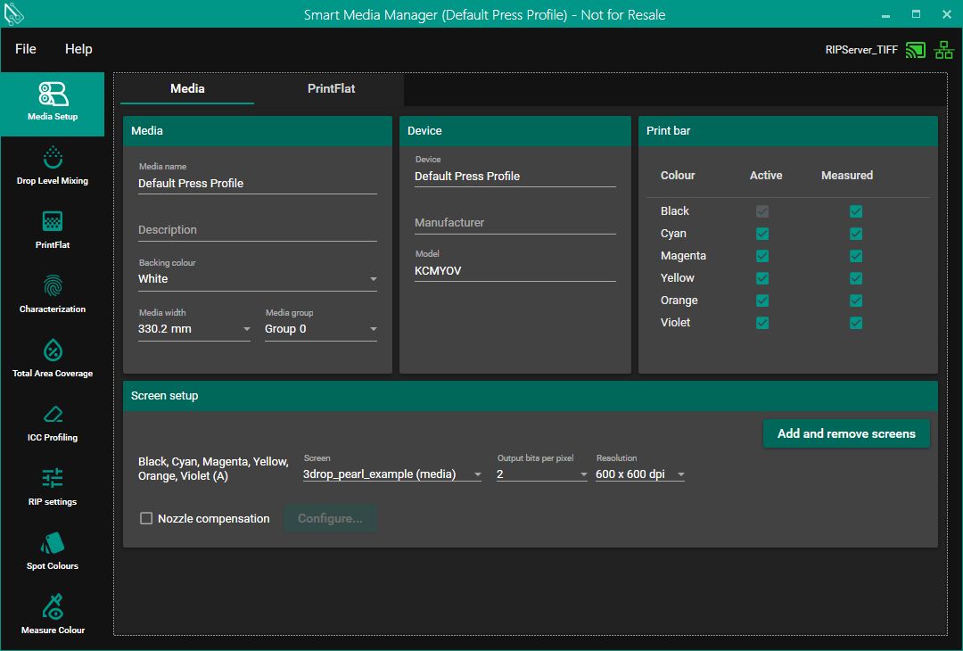
Media Name | This is free text to enter a name for your media. |
Description | This is free text to enter a description for your media. |
Backing Color | A selection of backing color options. |
Media Width | A selection of available media widths. |
Screen Setup | For each colorant, you can choose the Screen, Output Bits Per Pixel, and Resolution. |
Print Bars | This section allows the user to select which ink channels should be printed and measured, and which should be ignored. Channels marked as ignored will not be used in Smart Media Manager (SMM) for dot gain correction, ink limiting, gray balance, or ICC profiling. However, these channels must still be included during the drop level and pinning stages. Ignored channels are excluded from both PrintFlat calibration and ICC profiling. In Smart Print Controller (SPC), ignored channels are excluded specifically from ICC profiling. |
Add White Backing | This will only be visible if you have white in the printer profile. When enabled it adds a white background to the target. |
Linearization only or Linearization and calibration | This setting is used by Smart Media Manager to determine the type of data you want to generate during the PrintFlat stage. You can choose to produce either:
|
Nozzle Compensation Enabled | Enabling this option allows you to open the Nozzle Correction Configuration window to set up and manage nozzle compensation settings (see below). |
Configure Nozzle Compensation | This button becomes active only when 'Nozzle Compensation Enabled' is checked. Clicking it will open the Nozzle Correction Configuration window, allowing you to set up or modify nozzle compensation settings. |
Screen Setup
This section allows the selection of screen, resolution etc.
Nozzle Compensation Configuration

Before and after nozzle compensation
This dialog allows the setup of the nozzle compensation settings. Once setup the OEM can supply a list of missing nozzles via the OPCUA interface,
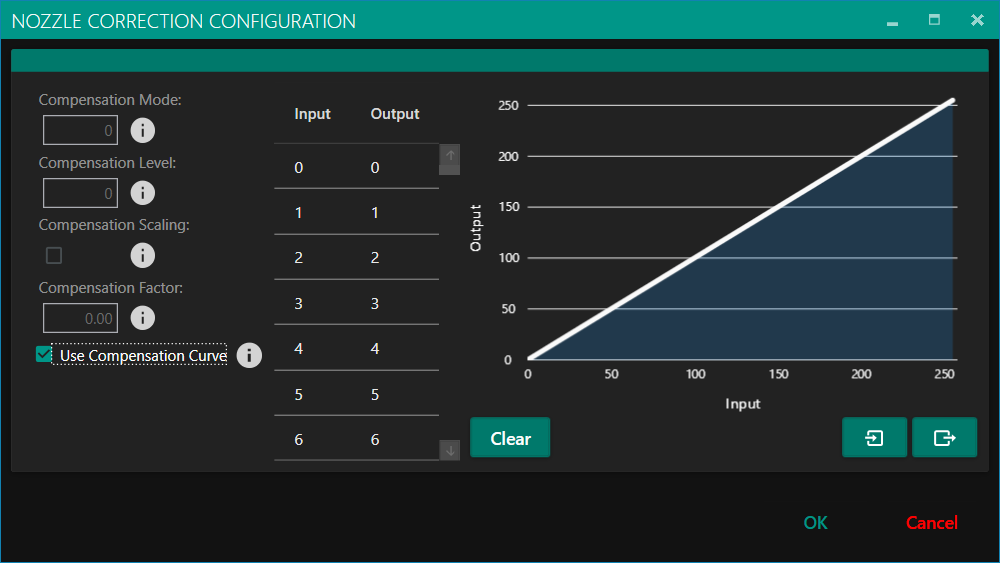
Compensation Mode | Defines how nozzle compensation is applied. Valid values are:
|
|---|---|
Compensation Level | Specifies how many neighboring nozzles are used for compensation. Acceptable values range from 0 to 5 (inclusive).
|
Compensation Scaling | When enabled, this option adjusts compensation based on the density of the failed nozzle. The screening process reduces the compensation accordingly. |
Compensation Factor | Sets the percentage of the failed nozzle’s density used to compensate its neighbors.
|
Use Compensation Curve | When enabled, this activates a compensation curve. If not selected, the curve will not be included in the screen configuration. |
Compensation Curve | A table of 256 values, each between 0 and 255, defining the compensation factor for every grey level. |